2026
Line Follower · Arduino · PID · Custom PCBLine-Following Robot
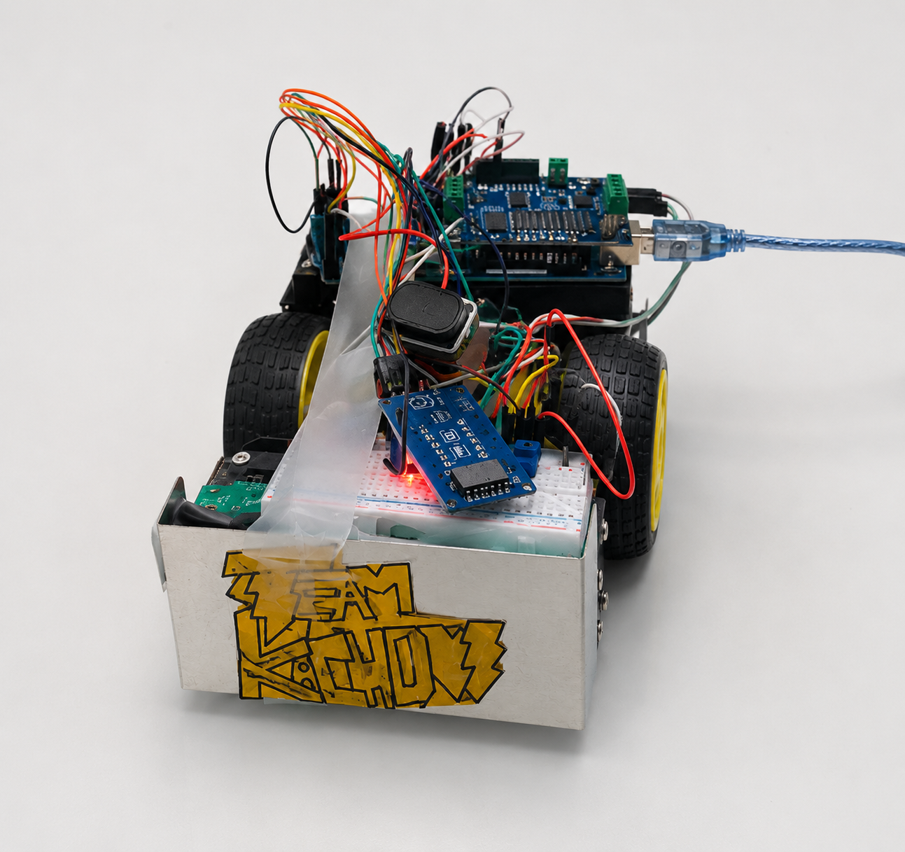
PID-tuned line follower that completed the course using seven photoresistors, a custom PCB, a 3D-printed chassis, and a light shield — finished the entire track with one manual nudge due to surface bumps.
01
Approach & key decisions
Sensors and interface
Seven photoresistors with 1 kΩ voltage dividers into Arduino analog A8–A14 distinguished black vs. white. Four potentiometers on analog inputs served as a live interface for adjusting Speed, P, I, and D.
Motor drive and code
Soldered a motor shield to the Arduino and implemented motor control code to command left/right motors independently for forward/backward motion.
Hardware iteration
Designed and 3D printed a new chassis, added a cardboard light shield to block ambient light, and replaced the breadboard sensor array with a custom PCB that set sensor/LED height and leveled them close to the ground.
Power integrity
Added a 9 V battery directly to Arduino VIN and removed the VIN jumper to prevent motor-induced brownouts that reset the microcontroller.
Calibration and tuning
Calibrated sensors on black (≈700–820) and white (≈590–650) surfaces; tuned SPID on the track to reduce oscillations and increase speed.
System spec
- Platform
- Arduino + motor shield
- Sensing
- 7 photoresistors with 1 kΩ dividers (A8–A14)
- Tuning interface
- 4 potentiometers for S, P, I, D
- Power
- Separate 9 V to VIN (jumper removed) to avoid brownouts
- Chassis
- 3D‑printed frame, cardboard light shield
02
Build gallery
03
Debugging timeline
Potentiometers
Clockwise turns decreased readings; counterclockwise increased them due to divider polarity.
Swap power and ground on the pot, or invert the analog mapping in code.
Photoresistors
Readings were skewed by shadows/bright ambient and excessive sensor height.
Added a cardboard light shield, added LEDs for a controlled source, and lowered sensor height a few millimeters.
Power
Motors induced brownouts that reset the MCU.
Fed Arduino VIN from a separate 9 V battery and removed the VIN jumper; runs stabilized and speed improved.
04
Results & final demo
- Completed the full track; required a single nudge mid‑course due to surface bumps.
- Final demo SPID: Speed 21, P 16, I 0, D 22.
- Calibration ranges: black ≈700–820, white ≈590–650.
05
The problem
Create a robot that could quickly and accurately follow a black line. Work spanned circuit design, Arduino programming, chassis design/assembly, and hardware implementation.
Next project