2025
Power Electronics · FOC · Motor Control · AltiumClosed-Loop BLDC Driver
Designed a 24 V field-oriented BLDC driver board and control loop holding ±0.3° position error under a 0.4 Nm step load.
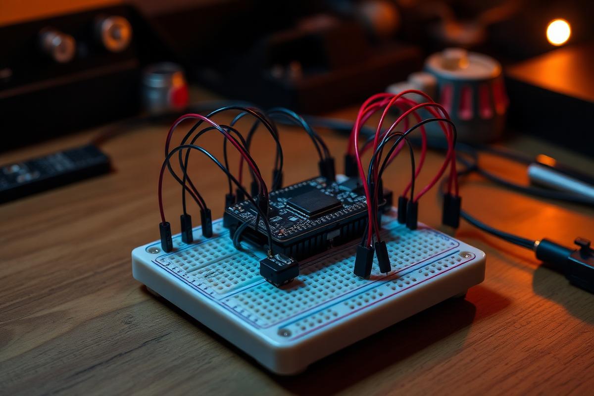
01
Approach & key decisions
Topology
Three-phase inverter with DRV8353 gate drivers into 60 V/100 A NexFETs, switching at 20 kHz. Low-side shunts on all three phases give full current reconstruction rather than the single-shunt estimate most hobby boards use.
Sensing and control
AS5047P magnetic encoder over SPI at 14-bit resolution feeds the FOC transform. Cascaded loops run current at 20 kHz, velocity at 2 kHz, and position at 1 kHz, all in fixed-point math on an STM32G474.
Layout discipline
4-layer stackup with an unbroken inner ground plane, gate loops under 8 mm, and the shunt sense pairs routed as differential Kelvin connections away from the switch node. This is the difference between a loop that converges and one that oscillates.
System spec
- MCU
- STM32G474 (170 MHz, hardware FPU)
- Gate driver
- TI DRV8353RS
- Encoder
- AS5047P, 14-bit, SPI @ 10 MHz
- Board
- 4-layer, 2 oz outer copper, 62 × 62 mm
- Control
- FOC, SVPWM, anti-windup PI cascade
- Tools
- Altium, MATLAB, Rigol DS1054Z, thermal camera
02
Build gallery
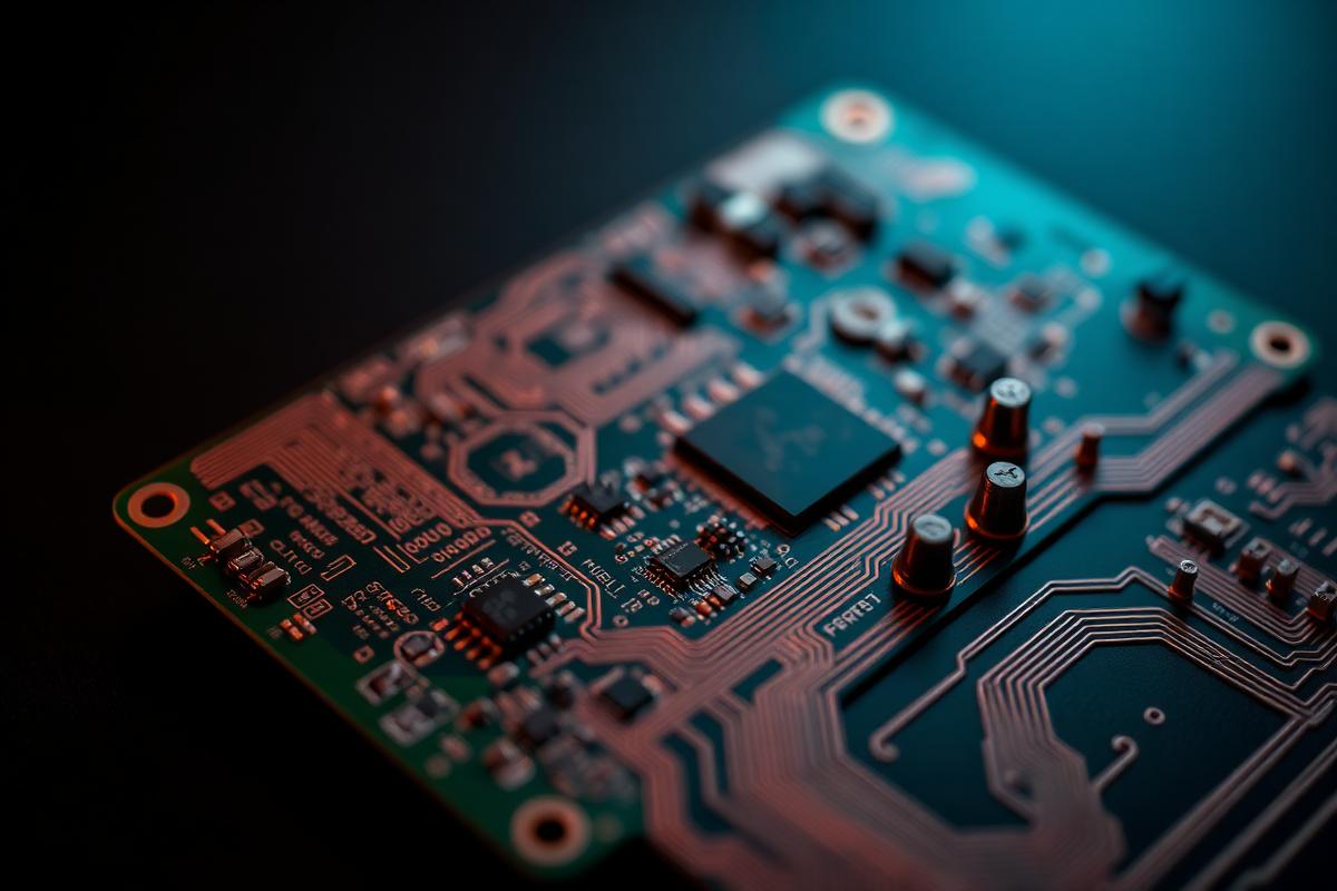
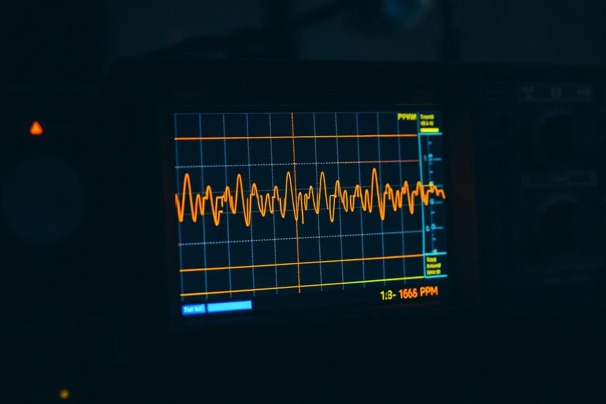
03
Debugging timeline
Rev A, day 1
Both high-side FETs on phase A failed short within two seconds of first spin-up.
Shoot-through from an inadequate dead-time setting. Raised hardware dead-time to 300 ns, added a bench current limit, and never again brought up a power stage without a series bulb.
Rev A, week 2
Current loop oscillated at roughly 4 kHz under any load.
The shunt sense traces ran alongside a switch node and picked up switching noise. Rerouted as a Kelvin differential pair on Rev B and added an RC filter matched to the amp bandwidth.
Rev B, week 1
Encoder reported random 180° jumps above 1500 rpm.
SPI reads landed inside the PWM switching edge. Moved the read to a timer-triggered event synchronized with the PWM center, which eliminated the fault entirely.
Rev B, week 3
Position drifted several degrees after long holds against load.
Integrator windup in the velocity PI. Added conditional-integration anti-windup and clamped the current command, dropping steady-state error to ±0.3°.
04
Results & final demo
- ±0.3° steady-state position error under a 0.4 Nm step disturbance.
- 12 A continuous phase current with no forced air, case temperature settling at 61 °C.
- Smooth 15 rpm crawl with no audible cogging, where the reference hobby ESC stalled below 90 rpm.
05
The problem
A robotics teammate needed a joint actuator that could hold position under sudden load rather than just spin at a commanded speed. Off-the-shelf hobby ESCs run open-loop trapezoidal commutation, which cogs at low speed and cannot report position, so I built a driver around field-oriented control instead.
Next project
Scout — Robot Guide Dog
Built Scout, a TurtleBot3-based robot guide dog with real-time crosswalk and traffic-light vision, LiDAR person-tracking, and a fail-safe velocity-gate stack — led perception and safety-control on a 4-person Human-Robot Interaction team.
Handheld Signal Analyzer
Built a pocket 1 MS/s scope and logic analyzer with a custom analog front end and machined aluminum enclosure, validated against a bench Rigol to within 1.8%.
Precision Current Source
Built a 0–20 mA Howland current pump with 0.05% FS error for sensor excitation and calibration benches.
915 MHz Matching Network
Designed and measured a π-network matching a LoRa PA into a PCB antenna, cutting VSWR from 3.8 to 1.3.
Lab Power Rail Monitor
USB-C multi-rail logger that watches 3.3 / 5 / 12 V benches for droop and glitch events down to 20 µs.
Line-Following Robot
PID-tuned line follower that completed the course using seven photoresistors, a custom PCB, a 3D-printed chassis, and a light shield — finished the entire track with one manual nudge due to surface bumps.