2025
Analog Front End · Product Design · CAD · DSPHandheld Signal Analyzer
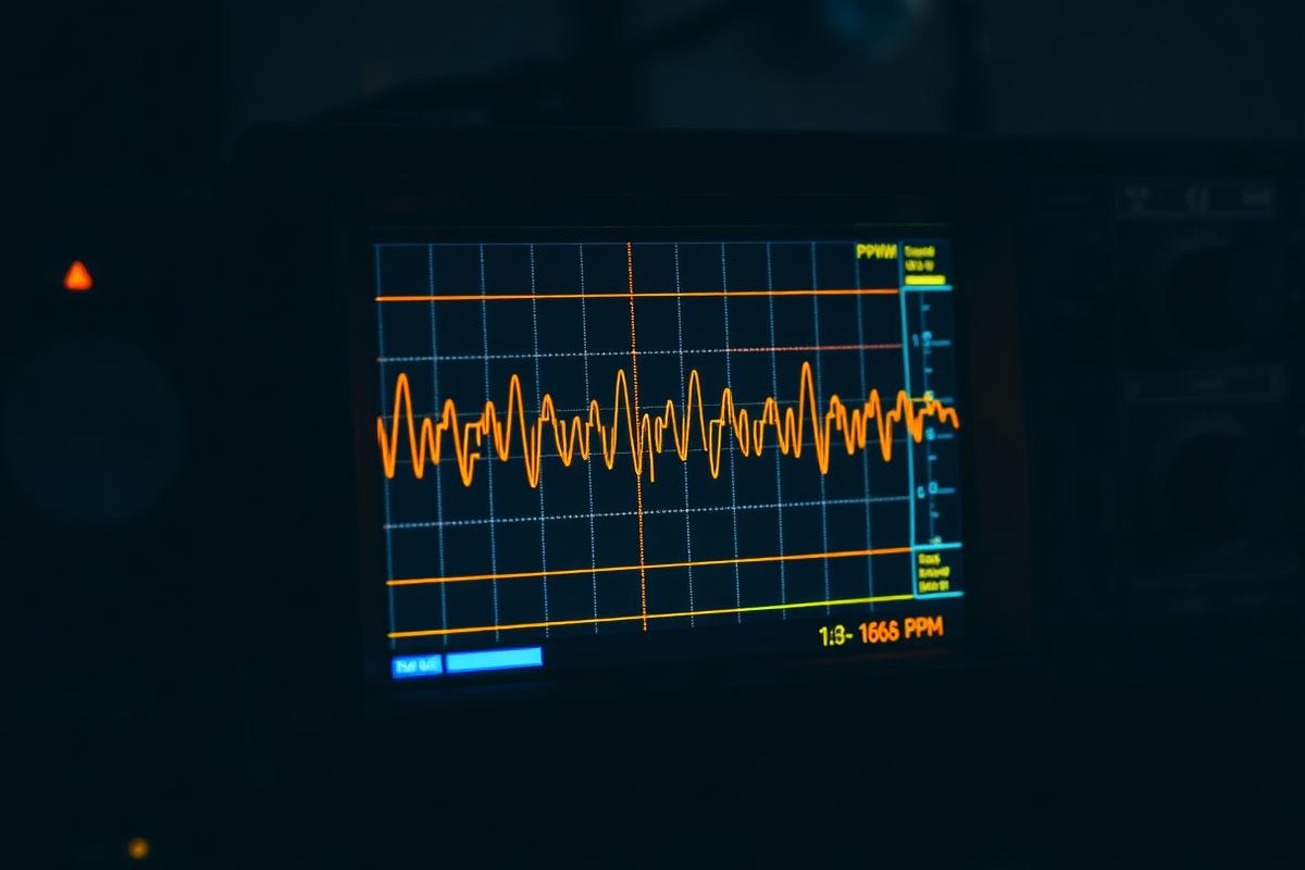
Built a pocket 1 MS/s scope and logic analyzer with a custom analog front end and machined aluminum enclosure, validated against a bench Rigol to within 1.8%.
01
Approach & key decisions
Analog front end
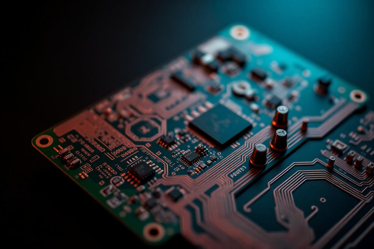
Compensated 1:1/1:10 divider into a programmable-gain amplifier, then a 400 kHz anti-alias filter feeding the 12-bit ADC. Clamp diodes and a series PTC survive ±50 V abuse, which is the failure mode every cheap USB scope shares.
Acquisition
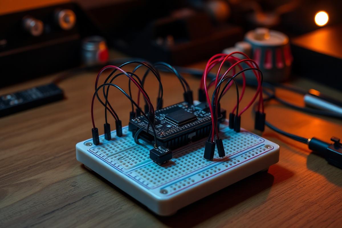
RP2040 PIO state machines capture the eight digital channels at 100 MS/s into a ring buffer over DMA, so the CPU only handles triggering and rendering. Analog capture runs at 1 MS/s per channel with hardware pre-trigger.
Enclosure and feel
Two-piece 6061 shell, chamfered edges, blind-tapped M2 posts so no fastener is visible from the front, and a captive 2.8" IPS display bonded behind a scratch-resistant window. Wall thickness dropped to 1.6 mm after an FEA pass at 1.9 mm showed excess margin.
System spec
- MCU
- RP2040, dual Cortex-M0+ @ 133 MHz
- Front end
- Compensated divider + PGA + 4th-order AAF
- ADC
- 12-bit, 1 MS/s per channel
- Digital
- 8 channels @ 100 MS/s via PIO + DMA
- Enclosure
- 6061-T6, CNC, clear anodize
- Tools
- Fusion 360, KiCad, Rigol DS1054Z, function gen
02
Build gallery
03
Debugging timeline
Prototype 1
Square waves showed 22% overshoot that the bench scope did not.
The divider compensation capacitor was mis-valued against the actual input capacitance. Swapped in a trimmer, tuned against a 1 kHz reference, then read back the final value and fitted a fixed part.
Prototype 1
Digital capture dropped samples above 40 MS/s.
DMA was contending with the display driver on the same bus. Moved framebuffer writes to core 1 with a dedicated DMA channel and staggered the priorities.
Prototype 2
Baseline noise doubled once the board was installed in the aluminum shell.
The chassis was floating and coupling into the analog island. Bonded the shell to signal ground at one screw boss near the input jack; noise floor returned to 1.4 mV RMS.
Prototype 2
Display window creaked and flexed under thumb pressure.
Bonded the window on a 0.4 mm recessed ledge with VHB rather than an unsupported edge glue joint, which also improved the dust seal.
04
Results & final demo
- Amplitude accuracy within 1.8% of a bench Rigol DS1054Z from 10 Hz to 400 kHz.
- 1.4 mV RMS noise floor on the most sensitive range, fully assembled.
- 5.5 hours of continuous capture on a 1200 mAh cell in a 96 × 62 × 18 mm package.
05
The problem
Debugging away from a bench meant guessing. I wanted an instrument I could actually carry: two analog channels plus eight digital lines, real attenuation and protection on the input, and an enclosure that felt like a product rather than a project box.
Next project
Scout — Robot Guide Dog
Built Scout, a TurtleBot3-based robot guide dog with real-time crosswalk and traffic-light vision, LiDAR person-tracking, and a fail-safe velocity-gate stack — led perception and safety-control on a 4-person Human-Robot Interaction team.
Closed-Loop BLDC Driver
Designed a 24 V field-oriented BLDC driver board and control loop holding ±0.3° position error under a 0.4 Nm step load.
Precision Current Source
Built a 0–20 mA Howland current pump with 0.05% FS error for sensor excitation and calibration benches.
915 MHz Matching Network
Designed and measured a π-network matching a LoRa PA into a PCB antenna, cutting VSWR from 3.8 to 1.3.
Lab Power Rail Monitor
USB-C multi-rail logger that watches 3.3 / 5 / 12 V benches for droop and glitch events down to 20 µs.
Line-Following Robot
PID-tuned line follower that completed the course using seven photoresistors, a custom PCB, a 3D-printed chassis, and a light shield — finished the entire track with one manual nudge due to surface bumps.